

Reverb Part 2—Natural Rooms with Allpass Rings

All posts in this series: Part 1, Part 2
Continuing from a previous post, today we'll be looking at another collection of reverb algorithms that I've implemented in my reverb plugin. With only a small increase in complexity over last time, we can get a reverb that grows in density over its duration, much as a real room would, and that sounds smoother and less metallic.
There are two key differences between the designs here and the Schroeder reverb I discussed previously: 1) in this design we will “nest” an allpass filter within another allpass filter, causing the echo density to grow over time, and 2) we will connect the ends of a chain of allpasses into one large “ring,” smoothing out the sound. Let's discuss how this all works!
Nested Allpass Filters
As we previously discussed, an allpass filter is created by a feedforward and feedback delay in series, with the gain of one of them being negative. This lets all frequencies through at equal amplitude, but delays different frequencies by different amounts, “smearing” or “blurring” the rhythmic attacks of an incoming sound, which is excellent for simulating reverberation. For the diagrams below, note that both the feedforward and feedback can use the same delay line — the design we're using is equivalent to two separate delays in series.
Schroeder found that the “smearing” from allpass filters multiplies the number of echoes about threefold. [1] However, the number of echoes is roughly constant over the duration of the reverberation. In a real room, echoes continually build up over the course of a reverb tail. To achieve this buildup, Barry Vercoe and Miller Puckette propose replacing the delay in an allpass filter with another allpass filter creating a “nested” structure. [2] Since an allpass filter will multiply the echoes that pass through it, taking the output of the inner allpass and feeding it back to the input will cause that multiplication to compound, increasing the number of echoes over time.
Below are diagrams of this design. Note that in addition to using a single allpass filter as the delay, we can use multiple allpasses in series, as well as combining them with simple delays. Gardner uses both options depicted below in the reverb algorithms we'll discuss today. [3] In the diagrams,
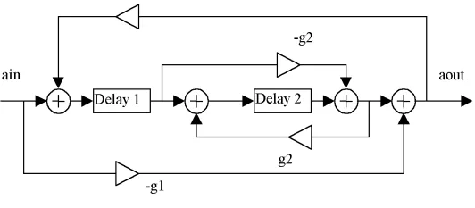
A block diagram of a nested allpass filter [4]
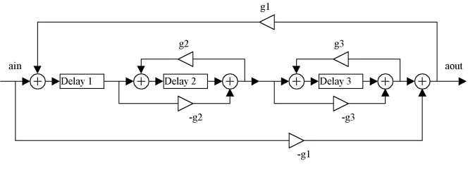
A block diagram of a double nested allpass filter [4:1]
Allpass Rings
To multiply the echoes even further, Gardner chains a mix of standard and nested allpass filters in series, and then feeds the end of that chain into the chain's input. [3:1] Last time, we placed a low-pass filter in the feedback path of individual comb filters. This time, Gardner suggests placing a single low-pass filter in the feedback path for the entire chain. In both contexts, the purpose is to cause higher frequencies to decay faster, similar to the effect of the atmosphere in a real room.
Gardner also suggests taking the output sound from multiple points along the allpass chain. These must be between allpass filters, rather than inside an allpass — taking it from inside an allpass will transform the allpass into a comb, producing an undesirable metallic quality. The output signals can be scaled in different proportions to customize the decay profile of the reverb, and the gain in the global feedback path can be used to scale the decay time overall.
Both the multiple outputs and the ring structure prevent this reverberator from being allpass. The ring structure in particular is a comb filter, which (as we discussed previously) introduces comb tooth-like peaks and valleys in the frequency spectrum. While Gardner does not go into depth about why the comb filtering is acceptable, my best understanding is that it's because the series allpasses add together to create a long delay time.
As I discussed here, and as the audio example below demonstrates, feedback combs with longer delay times create an audible “flutter,” and shorter times create a metallic sound. The long time in the allpass ring means no metallic sounds, and because the chain of nested allpasses multiplies the echo density so much, the flutter isn't meaningfully audible.
Gardner's Reverb Designs
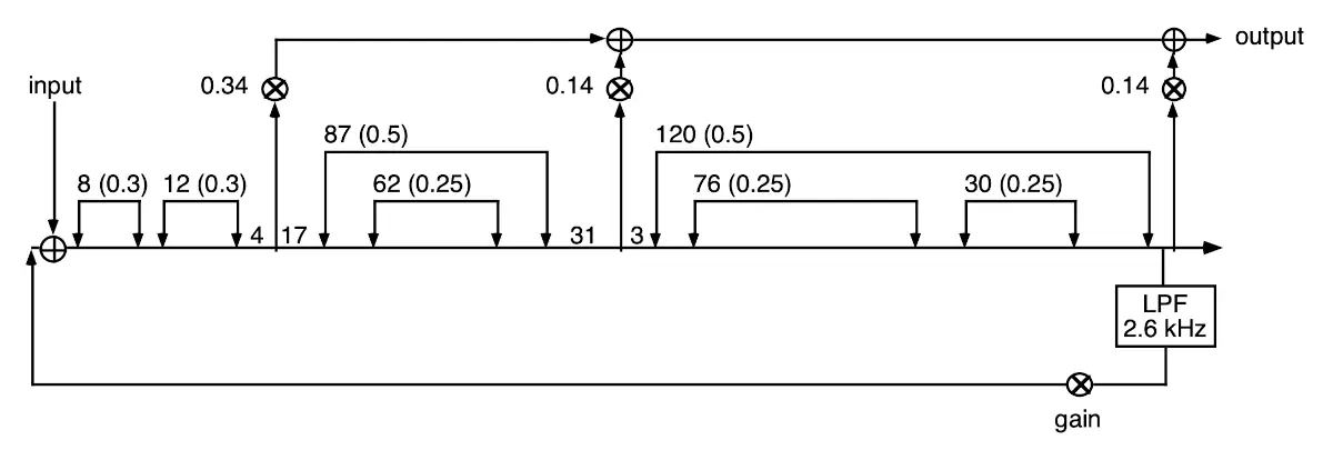
Below are the three designs Gardner gives. The small one is good for decay times between 0.38–0.57 seconds; the medium for 0.58–1.29 seconds; and the large for 1.30 seconds and above. Gardner does not find any particular rule for choosing decay times, noting that the process for designing the three topologies he describes was “purely empirical.” [3:2] As with designing Schroeder reverbs, a good starting point seems to be to avoid delay times that easily divide into each other; this ensures the delays do not rhythmically align. The first number next to a delay is the time in milliseconds, and the float value in parentheses is the gain.
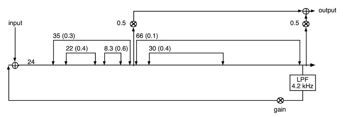
Small room reverberator [3:3]
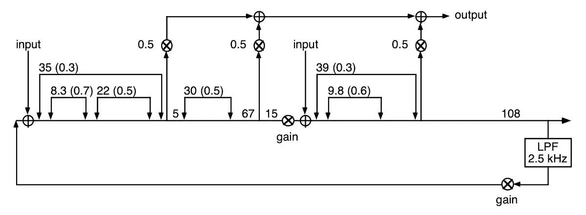
Medium room reverberator [3:4]
Large room reverberator [3:5]
Note that these designs have a mix of delays, allpasses, nested allpasses, and double nested allpasses. The medium reverberator also has two inputs, and applies the gain both in the feedback loop and in the middle of the allpass chain, directly before the second input.
Reverb Characteristics
Gardner describes these as “room” reverbs. While they are synthesized, not real rooms, it's still useful to look at the characteristics of the types of reverbs Gardner is emulating. First off, Sean Costello of Valhalla DSP describes room reverbs as having prominent early reflections.
Early reflections refer to sounds within the first 80 ms or so, followed by late reflections. Summarizing psychoacoustic research on the matter, Rungta et al. note that early reflections positively correlate with “the perception of auditory spaciousness,” are “very important in concert halls,” and can “improve speech clarity in rooms.” [5]
Rungta et al. also note that these early reflections help the listener hear the shape of the room. My best guess for why is because these reflections have traveled a short distance to the listener, maybe only reflecting a single time. This implies for “room”-type reverbs that we get a particularly strong sense of the room's dimensions. In my next post, I'll describe Dattorro's 1997 “plate”-style allpass ring, and we'll hear how that reverb sounds more amorphous, with less sense of space.
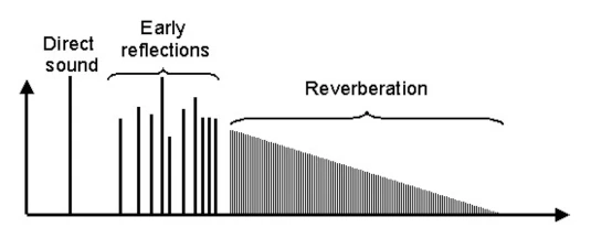
Direct sound, early reflections, and late reflections/reverberation; horizontal axis is time and vertical is amplitude [5:1]
In addition to these early reflections, Costello describes a dense sound and a short decay — these are usually smaller rooms than the reverb chambers in recording studios. Rooms also quickly build up echo density (here accomplished with the nested allpasses) and tend to be “colored,” i.e., they emphasize some frequencies over others. You may want to use an EQ on your reverb send track to reduce low frequencies on these algorithms, depending on your application. Costello suggests these may be useful for adding body to drums and acoustic instruments.
Postscript
These algorithms are all available in my algorithmic reverb plugin via the dropdown menu at the bottom. I also have Max/MSP abstractions of them available on my Codeberg. I would love to hear if you try them out!
As I mentioned, in my next post I'll cover the famous 1997 Dattorro plate algorithm that also uses an allpass ring structure. This is in Max/MSP as the [yafr2] abstraction, and in the Valley Audio “Plateau” module for VCV Rack, among numerous other places, and is likely based on an algorithm from the Lexicon 224/480 reverb units. I hope to see you then!
M. R. Schroeder, “Natural sounding artificial reverberation,” in Audio Engineering Society Convention 13, Audio Engineering Society, 1961. Accessed: Dec. 29, 2024. [Online]. Available: https://www.aes.org/e-lib/download.cfm?ID=343 ↩︎ ↩︎
Unfortunately this paper is unpublished, and I was only able to find William Gardner's description of it, [1:1] but here is the citation:
B. Vercoe and M. Puckette, “Synthetic Spaces — Artificial Acoustic Ambiance from Active Boundary Computation,” 1985, Music and Cognition Office at MIT Media Lab, Boston, MA. ↩︎
W. G. Gardner, “A realtime multichannel room simulator,” J. Acoust. Soc. Am, vol. 92, no. 4, p. 2395, 1992. Available: https://pubs.aip.org/asa/jasa/article/92/4_Supplement/2395/646024/A-real-time-multichannel-room-simulator ↩︎ ↩︎ ↩︎ ↩︎ ↩︎ ↩︎
H. Mikelson, “A Csound Multi-Effects Processor.” Accessed: Sept. 26, 2025. [Online]. Available: https://www.eumus.edu.uy/eme/ensenanza/electivas/csound/materiales/book_chapters/24mikelson/24mikelson.html ↩︎ ↩︎
A. Rungta, N. Rewkowski, R. Klatzky, and D. Manocha, “P-Reverb: Perceptual Characterization of Early and Late Reflections for Auditory Displays,” in 2019 IEEE Conference on Virtual Reality and 3D User Interfaces (VR), Mar. 2019, pp. 455–463. doi: 10.1109/VR.2019.8797914. Available: https://arxiv.org/pdf/1902.06880 ↩︎ ↩︎
---END OF TRANSMISSION---
Leave a Comment